|
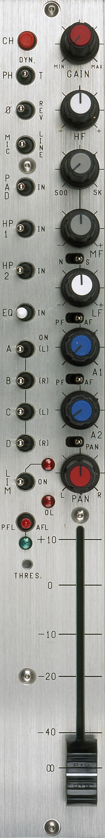
CS 208 v2 INPUT MODULE |
|||
|
Click
image to view larger in a new browser window.
|
|||
|
|
Left Section | ||
|
1. CH : |
Channel
Power (down = on) |
||
| 2. PH/DYN/T: | Phantom
power, no mic power, T (AB) power (Phantom power is normally 48 v, see layout A to change to 12 v). |
||
| 3. ø: | Phase
(audio only). ø = normal phase REV = reverse phase |
||
| 4. Mic/Line: | Microphone
or line level in. |
||
| 5. Pad: | Attenuator to reduce either mic or line input levels. | ||
| 6. HP 1: | High
pass filter, pre-transformer. |
||
| 7. HP 2: | High
pass filter, post transformer & preAmps. |
||
| 8. EQ: | Equalizer
bypass. Affects HF, MF & LF filters, not HP filters. |
||
| 9-12 A,B,C,D: | Channel
to mix bus assigns. L(left), R(right) indicate monitor & pan pot assignment.
|
||
| 13. LIM + LED: | The
limiter is a symmetrical peak detecting type & is completely out of
circuit when switched off. Threshold: See (15). Attack & release times
are preset internally (see layout A to change). The LED indicates limiter
action. |
||
| 14. PFL/AFL + LED: | Pre
fade listen or After fade listen (post fader). The switch is not momentary,
the LED serves as warning that PFL or AFL is selected. |
||
| 15. Thres: | Limiter
threshold. Clockwise = lower threshold. |
||
| 16. O/L: | Near
overload indicator. |
||
|
Right Section |
|||
| 17. Gain: | Mic/Line
preamp gain. |
||
| 18. HF: | High
frequency amplitude control. |
||
| 19. MF 500, 5k: | Mid-frequency
select. |
||
| 20. MF: | Mid-frequency
amplitude control. |
||
| 21. N/S: | N
= normal, S = side for M/S decoding. 'S' inverts phase to B & D busses allowing one pair of channels to be used with a M/S mic configuration and decoded to a L/R stereo signal. (This is an option, see separate application note.) |
||
|
22. LF: |
Low
frequency amplitude control. |
||
| 23. PF/AF: | Selects
pre or after fader for Aux 1 send. |
||
| 24. A1: | Aux
1 send (the aux sends are not affected by the ABCD mix bus switches).
|
||
| 25. PF/AF: | Selects
pre or after fader for Aux 2 send. |
||
| 26. A2: | Aux
2 send. |
||
| 27. Pan (switch): | Switching
the pan switch to the left disengages the pan pot. Crosstalk is therefore minimized and the output levels will remain equal. |
||
| 28. Pan (pot): | (L)
= A & or C (R) = B & or D |
||
|
29. Channel fader See specifications & application notes for further details. |
|||
|
|
|||
|
|
|
© Cooper Sound Systems, Inc.
|
|